TIM3 так изначально и планировал. Все ж из двух оставшихся 16 битных таймеров сделал 32 битный - раз есть такая возможность - надо попробовать, упрощает ж все. Частотомер удался, только протеус в конце подкачал - на высоких частотах тормозит, не измеряет, на низких измеряет. В принципе протеусом что-то можно посимулировать, все остальное надо в железе (лучше сразу, как подсказали).
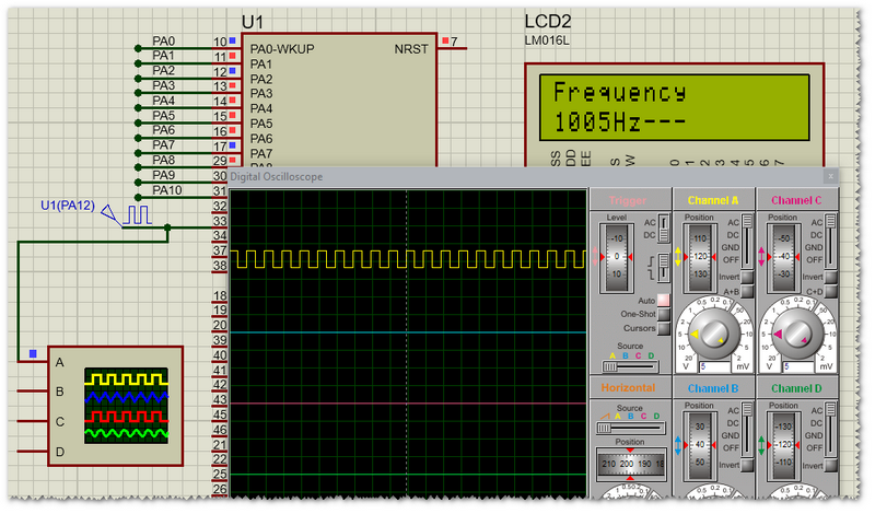
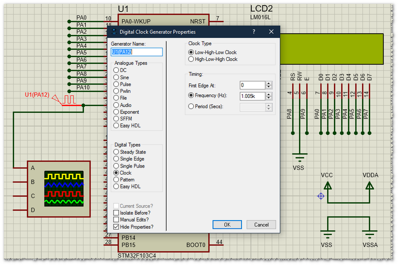
Задаем частоту входную 1005Гц:

Измеряем нашим частотомером:
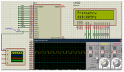
софтик:
заняло: Program Size: Code=928 RO-data=268 RW-data=12 ZI-data=1044
з.ы. "велосипед" заново изобретен, теперь меня возьмут на работу на частотомеропроизводящую фабрику
Задаем частоту входную 1005Гц:
Измеряем нашим частотомером:
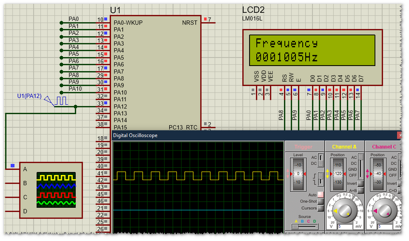
софтик:
Спойлер
Код: Выделить всё
#include "stm32f103x6.h"
#include "hd44780_driver.h"

volatile uint32_t msTicks;                                 // counts 1ms timeTicks
volatile uint32_t cntValue;
volatile uint8_t flagEndMeasure = 0;
char asc[20];

extern void Delay (uint32_t dlyTicks);
/*----------------------------------------------------------------------------
 * SysTick_Handler:
 *----------------------------------------------------------------------------*/
void SysTick_Handler(void)
{
    msTicks++;
}

/*----------------------------------------------------------------------------
 * Delay: delays a number of Systicks
 *----------------------------------------------------------------------------*/
void Delay (uint32_t dlyTicks)
{
    uint32_t curTicks;

    curTicks = msTicks;
    while ((msTicks - curTicks) < dlyTicks)
    {
        __NOP();
    }
}

void itoa1(uint32_t binval)
{
    uint32_t temp, val;
    uint8_t binc, atemp;
    val = binval;
    atemp = '0';
    temp = 1000000;
    while (val >= temp)
    {
        atemp++;
        val -= temp;
    }
    *(asc + 0) = atemp;
    atemp = '0';
    temp = 100000;
    while (val >= temp)
    {
        atemp++;
        val -= temp;
    }
    *(asc + 1) = atemp;
    atemp = '0';
    temp = 10000;
    while (val >= temp)
    {
        atemp++;
        val -= temp;
    }
    *(asc + 2) = atemp;
    atemp = '0';
    temp = 1000;
    while (val >= temp)
    {
        atemp++;
        val -= temp;
    }
    *(asc + 3) = atemp;
    atemp = '0';
    temp = 100;
    while (val >= temp)
    {
        atemp++;
        val -= temp;
    }
    *(asc + 4) = atemp;
    atemp = '0';
    binc = (char) val;
    while (binc >= 10)
    {
        atemp++;
        binc -= 10;
    }
    *(asc + 5) = atemp;
    binc += '0';
    *(asc + 6) = binc;
}

void InitTimers()
{
    TIM3->ARR = 1000-1; //1000
    TIM3->PSC = 8000-1; //8000000/8000 = 1000
    TIM3->CR2 |= TIM_CR2_MMS_0; //Enable - the Counter enable signal, CNT_EN, is used as trigger output (TRGO). It is
//useful to start several timers at the same time or to control a window in which a slave timer is
//enabled. The Counter Enable signal is generated by a logic OR between CEN control bit
//and the trigger input when configured in gated mode.
//When the Counter Enable signal is controlled by the trigger input, there is a delay on TRGO,
//except if the master/slave mode is selected (see the MSM bit description in TIMx_SMCR
//register).
    TIM3->DIER |= TIM_DIER_UIE; // Update interrupt enabled
    TIM3->CR1 |= TIM_CR1_CEN | TIM_CR1_DIR | TIM_CR1_OPM; //Counter used as downcounter
//Counter stops counting at the next update event (clearing the bit CEN) Counter enabled

    TIM1->PSC = 0;
	TIM1->ARR = 0xFFFF;
    TIM1->SMCR |= TIM_SMCR_ETF_1; // External trigger filter
//This bit-field then defines the frequency used to sample ETRP signal and the length of the
//digital filter applied to ETRP. The digital filter is made of an event counter in which N
//consecutive events are needed to validate a transition on the output: 0010: fSAMPLING=fCK_INT, N=4

    TIM1->SMCR |= TIM_SMCR_ECE | TIM_SMCR_TS_1; //External clock mode 2 enabled. The counter is clocked by any active edge on the ETRF
//002: Internal Trigger 2 (ITR2) TIM3_TRGO

    TIM1->SMCR |= TIM_SMCR_SMS_0 | TIM_SMCR_SMS_2; //101: Gated Mode - The counter clock is enabled when the trigger input (TRGI) is high. The
//counter stops (but is not reset) as soon as the trigger becomes low. Both start and stop of
//the counter are controlled.

    TIM1->CR2 |= TIM_CR2_MMS_1; //010: Update - The update event is selected as trigger output (TRGO). For instance a master
//timer can then be used as a prescaler for a slave timer.
    TIM1->CR1 |= TIM_CR1_CEN;

    TIM2->SMCR |= TIM_SMCR_SMS_1 | TIM_SMCR_SMS_2 | TIM_SMCR_SMS_0; //111: External Clock Mode 1 - Rising edges of the selected trigger (TRGI)
//clock the counter.

    TIM2->CR1 |= TIM_CR1_CEN;

    NVIC_EnableIRQ(TIM3_IRQn);
}

void TIM3_IRQHandler(void)
{
    TIM3->SR &= ~TIM_SR_UIF;
    cntValue = (uint32_t)TIM1->CNT | (uint32_t)TIM2->CNT << 16;
    flagEndMeasure = 1;
    TIM2->CNT=0;
    TIM1->CNT=0;
    TIM3->CR1 |= TIM_CR1_CEN;
}

int main(void)
{
    RCC->APB2ENR |= RCC_APB2ENR_IOPAEN | RCC_APB2ENR_TIM1EN;
    RCC->APB1ENR |= RCC_APB1ENR_TIM2EN | RCC_APB1ENR_TIM3EN;
    GPIOA->CRL |=  (GPIO_CRL_MODE0_1 |
                    GPIO_CRL_MODE1_1 |
                    GPIO_CRL_MODE2_1 |
                    GPIO_CRL_MODE3_1 |
                    GPIO_CRL_MODE4_1 |
                    GPIO_CRL_MODE5_1 |
                    GPIO_CRL_MODE6_1 |
                    GPIO_CRL_MODE7_1 );
    GPIOA->CRH |=  (GPIO_CRH_MODE8_1 |
                    GPIO_CRH_MODE9_1 |
                    GPIO_CRH_MODE10_1 |
                    GPIO_CRH_MODE12_1 |
                    GPIO_CRH_MODE12_0 );

    SysTick_Config(8000000UL / 1000);                  // SysTick 1 msec interrupts

    LCD(COM, 0x30);
    Delay(4);
    LCD(COM, 0x30);
    Delay(2);
    LCD(COM, 0x30);
    Delay(2);
    LCD(COM, 0x3C);
    Delay(2);
    LCD(COM, 0x0C);
    Delay(2);
    LCD(COM, 0x01);
    Delay(2);
    LCD(COM, 0x80);
    Delay(2);
    LCD_STRING("Frequency");
    LCD(COM, 0xC0);
    LCD_STRING("---------");

    InitTimers();

    while (1)
    {
        while(flagEndMeasure == 0);
        itoa1(cntValue);
        flagEndMeasure = 0;
        LCD(COM, 0xC0);
        LCD_STRING(asc);
        LCD_STRING("Hz");
        GPIOA->ODR ^=(uint16_t)(1<<10);
    }
}з.ы. "велосипед" заново изобретен, теперь меня возьмут на работу на частотомеропроизводящую фабрику