Хитро-умный аккумулятор.

Ремонт портативной техники - телефоны, КПК, навигаторы и типа того.
Ответить
Вымогатель припоя
Сообщения: 561
Зарегистрирован: Ср окт 23, 2019 08:41:11
Откуда: Саратов

Сообщение Vovan_sar »

tima_02, с кнопки - нет.
Контактная информация:
Реклама
Первый раз сказал Мяу!
Сообщения: 32
Зарегистрирован: Вт дек 14, 2021 23:41:06

Сообщение GdeMoi17Let »

[uquote="Vovan_sar",url="/forum/viewtopic.php?p=4142364#p4142364"]поищите по SALEAE Logic , Cypress, fx2lp[/uquote]
В общем, я снял логи когда с клавиатурой все нормально и когда глючит, но никакой особой разницы не обнаружил. Идут схожие циклические запросы. С помощью файла sluuaz4.pdf я примерно расшифровал их, но снова не нашел ничего на что следует обратить внимание.
Адрес 0x0B это BQ40z555, 0x09 это BQ24735.
Вот так выглядит цикл запросов к BQ40z555 когда не было глюка, расшифровка флагов примерная и не всех, только тех что мне показались значимыми, не уверен что правильно понял где там что:
Спойлер

Код: Выделить всё

write to 0x0B ack data: 0x00 		ManufacturerAccess
read to 0x0B ack data: 0x80 0x63	0110 0011 1000 0000
									XCHG (Bit 14): Charging disabled
										1 = Active
										0 = Inactive
									XDSG (Bit 13): Discharging disabled
										1 = Active
										0 = Inactive
									SEC1, SEC0 (Bits 9–8): SECURITY mode
										0, 0 = Reserved
										0, 1 = Full Access
										1, 0 = Unsealed
										1, 1 = Sealed
									BTP_INT (Bit 7): Battery Trip Point Interrupt. Setting and clearing this bit depends on various conditions.
									PRES (Bit 0): System present low
										1 = Active
										0 = Inactive

write to 0x0B ack data: 0x17 		CycleCount
read to 0x0B ack data: 0x14 0x00	20

write to 0x0B ack data: 0x3F 		CellVoltage1
read to 0x0B ack data: 0x62 0x10	4194 mV

write to 0x0B ack data: 0x3E 		CellVoltage2
read to 0x0B ack data: 0x60 0x10	4192 mV

write to 0x0B ack data: 0x3D 		CellVoltage3
read to 0x0B ack data: 0x66 0x10	4198 mV

write to 0x0B ack data: 0x3C 		CellVoltage4
read to 0x0B ack data: 0x64 0x10	4196 mV

write to 0x0B ack data: 0x16 		BatteryStatus
read to 0x0B ack data: 0xE0 0x48	0100 1000 1110 0000  
									TCA (Bit 14): Terminate Charge Alarm. 
									TDA (Bit 11): Terminate Discharge Alarm
									INIT (Bit 7): Initialization:		Gauge initialization is complete. 
									DSG (Bit 6): Discharging or Relax:	Battery is in DISCHARGE or RELAX mode.  
									FC (Bit 5): Fully Charged:			Battery fully charged when GaugingStatus()[FC] = 1

write to 0x0B ack data: 0x0D 		RelativeStateOfCharge 
read to 0x0B ack data: 0x64 0x00	100%

write to 0x0B ack data: 0x15 		ChargingVoltage
read to 0x0B ack data: 0x00 0x00	0 mV

write to 0x0B ack data: 0x08 		Temperature
read to 0x0B ack data: 0xB9 0x0B	3001

write to 0x0B ack data: 0x10 		FullChargeCapacity
read to 0x0B ack data: 0xDD 0x0A	2781 mAh

write to 0x0B ack data: 0x0F 		RemainingCapacity
read to 0x0B ack data: 0xDC 0x0A	2780 mAh

write to 0x0B ack data: 0x03 		BatteryMode
read to 0x0B ack data: 0x01 0x60	0110 0000 0000 0001
									CAPM (Bit 15): CAPACITY Mode (R/W) 0 = Report in mA or mAh (default)
									CHGM (Bit 14): CHARGER Mode (R/W) 1 = Disables ChargingVoltage() and ChargingCurrent() broadcasts to the host and smart battery charger (default)
									AM (Bit 13): ALARM Mode (R/W) 1 = Disables alarm warning broadcasts to the host and smart battery charger
									CF (Bit 7): Condition Flag (R) 0 = Battery OK
									ICC (Bit 0): Internal Charge Controller (R) 1 = Function is supported.

write to 0x0B ack data: 0x0A 		Current
read to 0x0B ack data: 0x00 0x00	0 mA

write to 0x0B ack data: 0x0B 		AverageCurrent
read to 0x0B ack data: 0x00 0x00	0 mA

write to 0x0B ack data: 0x09 		Voltage	
read to 0x0B ack data: 0x8B 0x41	16779 mV

write to 0x0B ack data: 0x14 		ChargingCurrent
read to 0x0B ack data: 0x00 0x00	0 mA

write to 0x0B ack data: 0x21 		DeviceName
read to 0x0B ack data: 0x07 0x41 0x43 0x31 0x34 0x42 0x38 0x4B
Вот так при наличии глюка:
Спойлер

Код: Выделить всё

write to 0x0B ack data: 0x00 		ManufacturerAccess
read to 0x0B ack data: 0x81 0x43	0100 0011 1000 0001
									XCHG (Bit 14): Charging disabled
										1 = Active
										0 = Inactive
									XDSG (Bit 13): Discharging disabled
										1 = Active
										0 = Inactive
									SEC1, SEC0 (Bits 9–8): SECURITY mode
										0, 0 = Reserved
										0, 1 = Full Access
										1, 0 = Unsealed
										1, 1 = Sealed
									BTP_INT (Bit 7): Battery Trip Point Interrupt. Setting and clearing this bit depends on various conditions.
									PRES (Bit 0): System present low
										1 = Active
										0 = Inactive

write to 0x0B ack data: 0x17 		CycleCount
read to 0x0B ack data: 0x14 0x00	20

write to 0x0B ack data: 0x3F 		CellVoltage1
read to 0x0B ack data: 0x55 0x10	4181 mV

write to 0x0B ack data: 0x3E 		CellVoltage2
read to 0x0B ack data: 0x52 0x10	4178 mV

write to 0x0B ack data: 0x3D 		CellVoltage3
read to 0x0B ack data: 0x59 0x10	4185 mV

write to 0x0B ack data: 0x3C 		CellVoltage4
read to 0x0B ack data: 0x57 0x10	4183 mV

write to 0x0B ack data: 0x16 		BatteryStatus
read to 0x0B ack data: 0xE0 0x00	0000 0000 1110 0000
									INIT (Bit 7): Initialization:		Gauge initialization is complete. 
									DSG (Bit 6): Discharging or Relax:	Battery is in DISCHARGE or RELAX mode.  
									FC (Bit 5): Fully Charged:			Battery fully charged when GaugingStatus()[FC] = 1

write to 0x0B ack data: 0x0D 		RelativeStateOfCharge
read to 0x0B ack data: 0x64 0x00	100%

write to 0x0B ack data: 0x15 		ChargingVoltage
read to 0x0B ack data: 0x00 0x00

write to 0x0B ack data: 0x08 		Temperature
read to 0x0B ack data: 0xA0 0x0B	2976

write to 0x0B ack data: 0x10 		FullChargeCapacity
read to 0x0B ack data: 0xDD 0x0A	2781 mAh

write to 0x0B ack data: 0x0F 		RemainingCapacity
read to 0x0B ack data: 0xDC 0x0A	2780 mAh

write to 0x0B ack data: 0x03 		BatteryMode
read to 0x0B ack data: 0x01 0x60	0110 0000 0000 0001
									CAPM (Bit 15): CAPACITY Mode (R/W) 0 = Report in mA or mAh (default)
									CHGM (Bit 14): CHARGER Mode (R/W) 1 = Disables ChargingVoltage() and ChargingCurrent() broadcasts to the host and smart battery charger (default)
									AM (Bit 13): ALARM Mode (R/W) 1 = Disables alarm warning broadcasts to the host and smart battery charger
									CF (Bit 7): Condition Flag (R) 0 = Battery OK
									ICC (Bit 0): Internal Charge Controller (R) 1 = Function is supported.


write to 0x0B ack data: 0x0A 		Current
read to 0x0B ack data: 0x00 0x00	0 mA

write to 0x0B ack data: 0x0B 		AverageCurrent
read to 0x0B ack data: 0x00 0x00	0 mA

write to 0x0B ack data: 0x09 		Voltage	
read to 0x0B ack data: 0x57 0x41	16727

write to 0x0B ack data: 0x14 		ChargingCurrent
read to 0x0B ack data: 0x00 0x00	0 mA

write to 0x0B ack data: 0x21 		DeviceName
read to 0x0B ack data: 0x07 0x41 0x43 0x31 0x34 0x42 0x38 0x4B
Из этих логов удалены запросы к BQ24735 и с десяток запросов 0x0A (Current), они бывало шли по три подрят, что во время глюка, что без него их примерно одинаковое количество.
Запросы к BQ24735, вот примерно что получилось:
Спойлер

Код: Выделить всё

write to 0x09 ack data: 0x3F 		InputCurrent
read to 0x09 ack data: 0x00 0x18	6144 mA?????

write to 0x09 ack data: 0x12 		ChargeOption
read to 0x09 ack data: 0x9B 0x18	0001 1000 1001 1011
									[15] ACOK Deglitch Time Adjust
										0: ACOK rising edge deglitch time 150 ms
									[14:13] WATCHDOG Timer Adjust
										00: Disable Watchdog Timer
									[12:11] BAT Depletion Comparator Threshold Adjust
										11: Falling Threshold = 70.97% of voltage regulation limit (approximately 2.981 V/cell) < default at POR>
									[10] EMI Switching Frequency Adjust
										0: Reduce PWM switching frequency by 18% <default at POR>
									[9] EMI Switching Frequency Enable 
										0: Disable adjust PWM switching frequency <default at POR>
									[8] IFAULT_HI Comparator Threshold Adjust
										0: function is disabled
									[7] IFAULT_LOW Comparator Threshold Adjust
										1: 230 mV
									[6] LEARN Enable
										0: Disable LEARN Cycle <default at POR>
									[5] IOUT Selection
										0: IOUT is the 20x adapter current amplifier output <default at POR>
									[4] AC Adapter Indication (Read Only)
										1: AC adapter is present (ACDET > 2.4 V)
									[3] BOOST Enable
										1: Enable Turbo Boost function
									[2] Boost Mode Indication (Read Only)
										0: Charger is not in boost mode <default at POR>
									[1] ACOC Threshold Adjust
										1: 3.33x of input current regulation limit <default at POR>
									[0] Charge Inhibit
										1: Inhibit Charge
Логи делались при подключенном шнуре и заряженной на 100% батарее.

На что стоит обратить внимание или может изменить условия при записи лога?
Заказл CP2112 приедет уже после нового года, может с его помощью удастся выяснить больше.
Реклама
Встал на лапы
Сообщения: 138
Зарегистрирован: Ср ноя 10, 2021 18:46:32

Сообщение vsuper »

Есть несколько вопросов:
1) Как узнать какая микросхема установлена в батарее, не вскрывая ее?
2) В логе указано "CycleCount: 1", что это означает? Предполагаю что это количество циклов заряда, но хотелось бы узнать наверняка. (Если это так, то продавец точно обнулил перед отправкой)
3) Как через be2works убрать ошибки и запустить батарею?
Cycle count 1 скорее всего действительно сброшена. У вас нет флагов с ошибками контроллера , INIT, DGG, это нормальное состояние. FD- полностью разряжена. Это единственная странность так как в таком случае оставшаяся емкость обычно =0.
Открыл глаза
Сообщения: 47
Зарегистрирован: Вт сен 28, 2021 17:06:07
Откуда: Украина, Харьковская обл.

Сообщение tima_02 »

[uquote="vsuper",url="/forum/viewtopic.php?p=4150847#p4150847"]
Есть несколько вопросов:
1) Как узнать какая микросхема установлена в батарее, не вскрывая ее?
2) В логе указано "CycleCount: 1", что это означает? Предполагаю что это количество циклов заряда, но хотелось бы узнать наверняка. (Если это так, то продавец точно обнулил перед отправкой)
3) Как через be2works убрать ошибки и запустить батарею?
Cycle count 1 скорее всего действительно сброшена. У вас нет флагов с ошибками контроллера , INIT, DGG, это нормальное состояние. FD- полностью разряжена. Это единственная странность так как в таком случае оставшаяся емкость обычно =0.[/uquote]
Спасибо за Ваш ответ. Подскажите пожалуйста, если по логам нету ошибки контроллера, почему в aida64 не показывает износа и в трее было расчетное время около 6 часов, что указывало на вполне отличную батарею? Как можно заставить отображать реальные данные? И еще вопрос, в поиске по модели батареи нашел зарубежный форум, где в такой же батареи просто заменили элементы и батарея оказалась рабочая, без программирования или разблркировки контроллера. Если по моим логам контроллер не заблокирован, могу ли я заменить просто элементы и надеятся что батарея вновь заработает или все таки нужно будет программно запускать ее? Из программного оборудования только cp2112. Заранее огромное спасибо за Вашу помощь
Реклама
Эиком - электронные компоненты и радиодетали
Встал на лапы
Сообщения: 138
Зарегистрирован: Ср ноя 10, 2021 18:46:32

Сообщение vsuper »

Спасибо за Ваш ответ. Подскажите пожалуйста, если по логам нету ошибки контроллера, почему в aida64 не показывает износа и в трее было расчетное время около 6 часов, что указывало на вполне отличную батарею? Как можно заставить отображать реальные данные? И еще вопрос, в поиске по модели батареи нашел зарубежный форум, где в такой же батареи просто заменили элементы и батарея оказалась рабочая, без программирования или разблркировки контроллера. Если по моим логам контроллер не заблокирован, могу ли я заменить просто элементы и надеятся что батарея вновь заработает или все таки нужно будет программно запускать ее? Из программного оборудования только cp2112. Заранее огромное спасибо за Вашу помощь
Aida высчитывает износ как соотношение между Design Capacity и Full Charge Capacity, если был сброс циклов то и емкость была сброшена на полную и не соответствует реальной емкости банок, надо прогнать несколько циклов тогда контроллер может откалиброваться. Заменить элементы можно, лучше паралельно подпаяв новые а потом отпаять старые, если просто отключить, то контроллер может заблокироваться
Реклама
Встал на лапы
Сообщения: 100
Зарегистрирован: Пн янв 03, 2022 05:45:18

Сообщение icespirit »

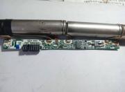
Аккумулятор моего ноутбука стареет.Разобрал корпус и заменил батарею 18650.Но батарея не имеет выхода :(
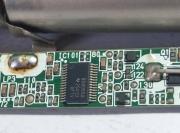
Проверял плату управления АКБ, на ней микросхема BQ8055A.
Путем поиска я обнаружил, что BE2WORK может это исправить.Но я нашел (v4.52_Bohol_fu11-pw_radiokot) только эту версию BE2WORKS, и она не поддерживает чип BQ8055A.У кого более поздняя версия программного обеспечения BE2WORKS? И поддерживает BQ8055A, пришлите, пожалуйста, мне копию?
Или подскажите как активировать BQ8055A

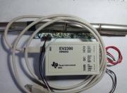
У меня EV2300, но мне не хватает программного обеспечения для поддержки BQ8055A.

Спасибо за помощь
Моя электронная почта: daisizhou # sina.com # = @
Изображение
Изображение
Изображение
Реклама
Родился
Сообщения: 2
Зарегистрирован: Ср янв 05, 2022 22:32:33

Сообщение vadim3930 »

Добрый вечер. Подскажите пожалуйста что может быть не так.
После перепаковки банок батарейка не работает.
Батарейка AS10D81 на контроллере bq20z955.
Работал Be2works (не жадной ) и cp2112
Подскажите что ей не нравится.

DesignCapacity: 4400 mAh
FullChargeCapacity: 3729 mAh
CycleCount: 140
Date: 2012.06.30 yyyy.mm.dd
DesignVoltage: 10800 mV
ManufName: LGC
DeviceName: AS10D81
SerialNumber: 1CD4
ChargingCurrent: 0 mA
ChargingVoltage: 0 mV
DeviceChemistry: LION
Temperature: 23,9 C
Voltage: 11795 mV
Current: 0 mA
RelativeSOC: 84%
AbsoluteSOC: 71%
RemainingCapacity: 3106 mAh
VCELL4: 0000 mV
VCELL3: 3949 mV
VCELL2: 3923 mV
VCELL1: 3922 mV
SpecificationInfo: 0031 Hex
Battery Status:
TCA|TDA|INIT|DSG|

MaxError: 1%
Operation Status:
DSG|VOK|QEN|
Safety Status: OK
PFStatus: OK
FETControl: 0000
Update Status: 14
Qmax Cell0: 4444
Qmax Cell1: 4377
Qmax Cell2: 4281
Qmax Cell3: 4400
Qmax Pack : 4281
Cell0 R_a flag : 0055
Cell1 R_a flag : 0000
Cell2 R_a flag : 0055
Cell3 R_a flag : FF55
Device Type: 0955
Firmware Version: 3.02
Hardware Version: A6
Manufacturer Status:
FET1|ST3|ST2|ST1|ST0|
Chemistry ID: 0206
Родился
Сообщения: 9
Зарегистрирован: Ср янв 05, 2022 04:01:12

Сообщение susliks »

Если из архивa в которого есть файл dat весом 10Мб то эта версия губит адаптер.
Встал на лапы
Сообщения: 100
Зарегистрирован: Пн янв 03, 2022 05:45:18

Сообщение icespirit »

Это информация, которую я прочитал с BE2WORKS, а BE2WORKS не поддерживает BQ8055A.
jjjjjjjjjjjj.jpg
(136.16 КБ) 344 скачивания
Последний раз редактировалось icespirit Пт янв 07, 2022 04:45:19, всего редактировалось 1 раз.
Родился
Сообщения: 2
Зарегистрирован: Ср янв 05, 2022 22:32:33

Сообщение vadim3930 »

После того когда посадил SP на GND появилось

Safety Status: PF|
PFStatus: PFIN|

И не удаляются пока не разъединишь контакты SP на GND.
Что не так.


MaxError: 1%
Operation Status:
PRES|DSG|VOK|QEN|
Safety Status:
PF|
PFStatus:
PFIN|
Charging Status:
RSVD10|
FETControl: 0000
Update Status: 14
Qmax Cell0: 4444
Qmax Cell1: 4377
Qmax Cell2: 4281
Qmax Cell3: 4400
Qmax Pack : 4281
Cell0 R_a flag : 0055
Cell1 R_a flag : 0000
Cell2 R_a flag : 0055
Cell3 R_a flag : FF55
Device Type: 0955
Firmware Version: 3.02
Hardware Version: A6
Manufacturer Status:
RSVD10|FET1|ST3|ST0|
Chemistry ID: 0206
Встал на лапы
Сообщения: 138
Зарегистрирован: Ср ноя 10, 2021 18:46:32

Сообщение vsuper »

Это информация, которую я прочитал с BE2WORKS, а BE2WORKS не поддерживает BQ8055A.
контроллер вроде не заблокирован, просто разряжена в 0
Держит паяльник хвостом
Аватара пользователя
Сообщения: 920
Зарегистрирован: Пн июн 13, 2016 19:37:24
Откуда: Perm

Сообщение daaar »

Удалось перепаковать аккумулятор от thinkpad x230 на bq8030. Правда если считать eeprom аккумулятор слетает к заводским(флаги FD, RTA, RCA) и приходится калибровать его заново (разряд-заряд). Аккумулятор кстати встал в x220 tablet, ошибок что не родной не выдает. На x230 tablet увы не заработал

Может быть кому-то будут полезны флаги be2works
СпойлерManufacturer Status

FET1, FET0— Indicates the state of the charge and discharge FETs
0,0 = Both charge and discharge FETs are on.
0,1 = CHG FET is off, DSG FET is on.
1,0 = Both charge and discharge FETs are off.
1,1 = CHG FET is on, DSG FET is off.
PF1, PF0— Indicates permanent failure cause when permanent failure is indicated by STATE3..STATE0
0,0 = Fuse is blown if enabled via DF:Configuration:Register(64):Permanent Fail Cfg 1..2(6..8 )
0,1 = Cell imbalance failure
1,0 = Safety voltage failure
1,1 = FET failure
STATE3, STATE2, STATE1, STATE0— Indicates the battery state.
0,0,0,0 = Wake Up
0,0,0,1 = Normal Discharge
0,0,1,1 = Pre-Charge
0,1,0,1 = Charge
0,1,1,1 = Charge Termination
1,0,0,0 = Fault Charge Terminate
1,0,0,1 = Permanent Failure
1,0,1,0 = Overcurrent
1,0,1,1 = Overtemperature
1,1,0,0 = Battery Failure
1,1,0,1 = Sleep
1,1,1,0 = Discharge Prohibited
1,1,1,1 = Battery Removed

BatteryMode

CapM— Sets the units used for capacity information and internal calculation.
0 = Reports in mA or mAh (default)
1 = Reports in 10 mW or 10 mWh
The following functions are instantaneously updated after a [CapM] change:
SBS:RemainingCapacityAlarm(0x01)
SBS:AtRate(0x04)
SBS:RemainingCapacity(0x0f)
SBS:FullChargeCapacity(0x10)
SBS:DesignCapacity(0x18)
The following functions are recalculated within 1 second after a [CapM] change:
SBS:RemainingTimeAlarm(0x02)
SBS:AtRateTimeToEmpty(0x06)
SBS:AtRateOK(0x07)
SBS:RunTimeToEmpty(0x11)
SBS:AverageTimeToEmpty(0x12)
SBS:BatteryStatus(0x16)
ChgM— Enables or disables the chip transmission of ChargingCurrent and ChargingVoltage messages to the Smart Battery Charger.
0 = Enable ChargingVoltage and ChargingCurrent broadcasts to the Smart Battery Charger by setting the [BCAST] bit in Operation Cfg B when charging is desired.
1 = Disable ChargingVoltage and ChargingCurrent broadcasts to the Smart Battery Charger. (default)
AM— Enables or disables AlarmWarning broadcasts to the host and Smart Battery Charger
0 = Enable AlarmWarning broadcast to host and Smart Battery Charger by setting the [BCAST] bit in Operation Cfg B (default). The chip sends the AlarmWarning messages to the SMBus Host and the Smart Battery Charger any time an alarm condition is detected.
1 = Disable AlarmWarning broadcast to host and Smart BatteryCharger. The chip does not master the SMBus, and AlarmWarning messages are not sent to the SMBus Host and the Smart Battery Charger for a period of no more than 65 seconds and no less than 45 seconds. [AM] is automatically cleared by the chip 60 seconds after being set to 1, independent of the [BCAST] bit.
PB— Sets the role of the battery pack. This flag is not used by the chip and should be set to 0.
CC— Enable or disable internal charge controller. This flag is not used by chip and should be set to 0.
CF— This flag is set if MaxError > CF MaxError Limit
0 = Battery OK
1 = Condition cycle requested
PBS— Primary battery support is not supported by chip and is fixed to 0.
ICC— This flag indicates whether the internal charge controller function is supported or not. This value is fixed to 1.

BatteryStatus

OCA— 1 = Over Charged Alarm
TCA— 1 = Terminate Charge Alarm
OTA— 1 = Over Temperature Alarm
TDA— 1 = Terminate Discharge Alarm
RCA— Remaining Capacity Alarm
1 = Remaining Capacity Alarm is set
RTA— Remaining Time Alarm
1 = Remaining Time Alarm is set
INIT— 1 = Initialization. The INIT flag is always set in normal operation.
DSG— Discharging
0 = chip is in charging mode
1 = chip is in discharging mode or relaxation mode, or valid charge
termination has occurred.
FC— 1 = Fully Charged
FD— 1 = Fully Discharged
EC3, EC2, EC1, EC0— Error Code, returns status of processed SBS function
0,0,0,0 = OK chip processed the function code with no errors detected.
0,0,0,1 = BUSY chip is unable to process the function code at this time.
0,0,1,0 = Reserved chip detected an attempt to read or write to a function code reserved by this version of the specification, or chip detected an attempt to access an unsupported optional manufacturer function code.
0,0,1,1 = Unsupported chip does not support this function code as defined in
this version of the specification.
0,1,0,0 = AccessDenied chip detected an attempt to write to a read-only function code.
0,1,0,1 = Over/Underflow chip detected a data overflow or underflow.
0,1,1,0 = BadSize chip detected an attempt to write to a function code with
an incorrect data block.
0,1,1,1 = UnknownError chip detected an unidentifiable error.

FETControl

OD— AFE GPOD pin control
0 = Disable GPOD pin (high-Z)
1 = Enable GPOD pin (open drain)
ZVCHG— Zero-volt (pre-charge) charge FET control
0 = Turn OFF pre-charge FET
1 = Turn ON pre-charge FET
CHG— Charge FET Control
0 = Turn OFF CHG FET. CHG FET does not turn off in discharge mode to protect the FET body diode.
1 = Turn ON CHG FET
DSG— Discharge FET Control
0 = Turn OFF DSG FET. It does not turn off in charge mode to protect the FET body diode.
1 = Turn ON DSG FET

Operation Status

CLL— (Cell Life Limit) 1 = Capacity of the pack fallen below Cell Life Limit threshold
DetW— (Deterioration Warning) 1 = Capacity of the pack fallen below Deterioration Warn Limit threshold
DetF— (Deterioration Fault) 1 = Capacity of the pack fallen below Deterioration Fault Limit threshold

SafetyStatus

OT1D— 1 = Discharge overtemperature on TS1 condition
OT1C— 1 = Charge overtemperature on TS1 condition
OCD— 1 = Discharge overcurrent condition
OCC— 1 = Charge overcurrent condition
OCD2— 1 = Discharge overcurrent condition 2
OCC2— 1 = Charge overcurrent condition 2
CUV— 1 = Cell undervoltage condition
COV— 1 = Cell overvoltage condition
PF— 1 = Permanent failure condition.
WDF— 1 = AFE watchdog condition
AOCD— 1 = AFE discharge overcurrent condition
SCC— 1 = Charge short-circuit condition
SCD— 1 = Discharge short-circuit condition

PFStatus

SUV— 1 = Safety Undervoltage permanent failure
SOCD— 1 = Discharge Safety Overcurrent permanent failure
SOCC— 1 = Charge Safety-Overcurrent permanent failure
AFE_P— 1 = Periodic AFE Communications permanent failure
AFE_C— 1 = Permanent AFE Communications failure
DFF— 1 = Data Flash Fault permanent failure
DFETF— 1 = Discharge-FET-Failure permanent failure
CFETF— 1 = Charge-FET-Failure permanent failure
CIM_R— 1 = Cell-Imbalance (At Rest method) permanent failure
SOT1D— 1 = Discharge Safety Overtemperature on TS1 permanent failure
SOT1C— 1 = Charge Safety Overtemperature on TS1 permanent failure
SOV— 1 = Safety-Overvoltage permanent failure
PFIN— 1 = External Input Indication of permanent failure

OperationStatus

PRES— 1 = PRES is low, indicating that the system is present (battery inserted).
FAS— 0 = Full access security mode
SS— 1 = Sealed security mode
CSV— 1 = Data flash checksum value has been generated
LDMD— Load mode for Impedance Track modeling. 0 = constant current, 1 = constant power
WAKE— 1 = bq20z40-R1/bq20z45-R1 WAKE mode
DSG— Replica of the SBS:BatteryStatus(0x16)[DSG] flag.
XDSG— 1 = Discharge fault
XDSGI— 1 = Discharge disabled due to a current issue
DSGIN— 1 = Discharge inhibited due to a high temperature issue
R_DIS— 1 = Ra Table resistance updates are disabled
VOK— 1 = Voltages are OK for a QMAX update
QEN— 1 = QMAX updates are enabled

ChargingStatus

XCHG— 1 = Charging disabled
CHGSUSP— 1 = Charging suspended
PCHG— 1 = Precharging
MCHG— 1 = Maintenance charging
LTCHG— 1 = Low temperature charging
ST1CHG— 1 = Standard temperature charging 1
ST2CHG— 1 = Standard temperature charging 2
HTCHG— High temperature charging
CB— 1 = Cell balancing in progress
OC— 1 = Overcharge fault

SafetyStatus2

OT2D— 1 = Discharge overtemperature condition on TS2
OT2C— 1 = Charge overtemperature condition on TS2

PFStatus2

CIM_A— 1 = Cell-Imbalance (Active method) permanent failure
SOT2D— 1 = Discharge Safety Overtemperature on TS2 permanent failure
SOT2C— 1 = Charge Safety Overtemperature in TS2 permanent failure

Permanent Fail Cfg 1

XPFVSHUT— If this bit is set AND any permanent failure happens AND the bq20z40-R1/bq20z45-R1
goes into shutdown, the SAFE pin is driven high.
XSUV— If this bit is set AND a safety undervoltage permanent failure occurs, the SAFE pin is driven high.
XSOCD— If this bit is set AND a discharge safety overcurrent permanent failure occurs, the SAFE pin is driven high.
XSOCC— If this bit is set AND a charge safety overcurrent failure occurs the SAFE pin is driven high.
XAFE_P— If this bit is set AND a periodic AFE-communications permanent failure occurs, the SAFE pin is driven high.
XAFE_C— If this bit is set AND an AFE-communications permanent failure occurs, the SAFE pin is driven high.
XDFF— If this bit is set AND a Data Flash Fault permanent failure occurs, the SAFE pin is driven high.
XDFETF— If this bit is set AND a DSG FET permanent failure occurs, the SAFE pin is driven high.
XCFETF— If this bit is set AND a CHG FET permanent failure occurs, the SAFE pin is driven high.
XCIM_R— If this bit is set AND a cell imbalance permanent failure occurs, the SAFE pin is driven high.
XSOT1D— If this bit is set AND safety over temperature on TS1 during discharge failure occurs the SAFE pin is driven high.
XSOT1C— If this bit is set AND safety over temperature on TS1 during charge failure occurs the SAFE pin is driven high.
XSOV— If this bit is set AND a safety overvoltage permanent failure occurs, the SAFE pin is driven high.
XPFIN— If this bit is set AND an external input indication permanent failure occurs, the SAFE pin is driven high.

Permanent Fail Cfg 2

XSOT2D— If this bit is set AND safety over temperature on TS2 during discharge failure occurs the SAFE pin is driven high.
XSOT2C— If this bit is set AND safety over temperature on TS2 during charge failure occurs the SAFE pin is driven high.
XCIM_A— If this bit is set AND a cell imbalance while active permanent failure occurs, the SAFE pin is driven high.

Non-Removable Cfg

OCD— Overcurrent in Discharge
OCC— Overcurrent in Charge
AOCD— AFE Overcurrent in Discharge
ASCC— Short Circuit in Charge
ASCD— Short Circuit in Discharge

Saved PF Flags 1

PFVSHUT— 1 = Another permanent failure has occurred AND the device went into shutdown after that event
SUV— 1 = Safety Undervoltage permanent failure
SOCD— 1 = Safety Overcurrent in Discharge permanent failure
SOCC— 1 = Safety Overcurrent in Charge permanent failure
AFE_P— 1 = Periodic AFE-Communications permanent failure
AFE_C— 1 = AFE-Communications permanent failure
DFF— 1 = Data Flash Fault permanent failure
DFETF— 1 = Discharge FET permanent failure
CFETF— 1 = Charge FET permanent failure
CIM— 1 = Cell-Imbalance permanent failure
SOTD— 1 = Discharge Safety Overtemperature permanent failure
SOTC— 1 = Charge Safety Overtemperature permanent failure
SOV— 1 = Safety Overvoltage permanent failure
PFIN— 1 = External PFIN Input Indication of a permanent failure
SOT2D— 1 = Safety over temperature on TS2 during discharge failure
SOT2C— 1 = Safety over temperature on TS2 during charge failure
CIM_A— 1 = Cell imbalance while active permanent failure
Контактная информация:
Родился
Сообщения: 8
Зарегистрирован: Сб дек 18, 2021 11:16:44

Сообщение sergey18 »

Правда если считать eeprom аккумулятор слетает к заводским
Аналогично на АКБ от Lenovo X201.

daaar, на вашей батарее зарядное напряжение 12900 или 12600?
Держит паяльник хвостом
Аватара пользователя
Сообщения: 920
Зарегистрирован: Пн июн 13, 2016 19:37:24
Откуда: Perm

Сообщение daaar »

sergey18, 12600

Осталось починить ноутбук, зарядка чего-то не идет (на заведомо живом аккумуляторе тоже самое)
Контактная информация:
Родился
Сообщения: 8
Зарегистрирован: Сб дек 18, 2021 11:16:44

Сообщение sergey18 »

daaar, могу я вас попросить скинуть мне прошивку? Моя прошивка на 12900, а я давно ищу на 12600.
Держит паяльник хвостом
Аватара пользователя
Сообщения: 920
Зарегистрирован: Пн июн 13, 2016 19:37:24
Откуда: Perm

Сообщение daaar »

sergey18, у меня есть cp2112. Если расскажите как, то скину
Контактная информация:
Родился
Сообщения: 9
Зарегистрирован: Ср янв 05, 2022 04:01:12

Сообщение susliks »

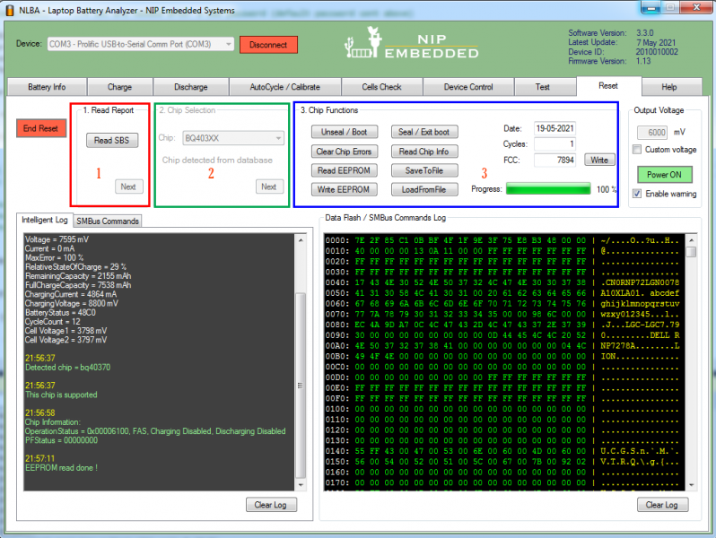
Появился еще такой NLBA-1 но надо продюжить с CP2112.

пробовал продюжит с помощью этово но надо эмулятор тогда зделать - https://github.com/pgsamila/HIDtoComPort

Изображение
Родился
Сообщения: 8
Зарегистрирован: Сб дек 18, 2021 11:16:44

Сообщение sergey18 »

daaar, у вас есть установленный Be2works?
Держит паяльник хвостом
Аватара пользователя
Сообщения: 920
Зарегистрирован: Пн июн 13, 2016 19:37:24
Откуда: Perm

Сообщение daaar »

sergey18, да, тот что только под XP работает
Контактная информация:
Родился
Сообщения: 8
Зарегистрирован: Сб дек 18, 2021 11:16:44

Сообщение sergey18 »

daaar, надо соединить CP2112 с АКБ, выбрать bq8030 и нажать на скачать прошивку (зленая стрелка сверху)
Ответить

Вернуться в «Дохлые потаскунчики»